I have spoken in a previous blog post about some issues with Apple hardware design
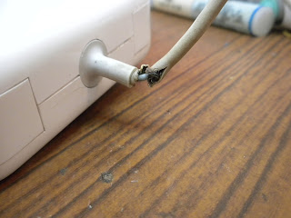
here. To briefly recap, it is of my beleif that in general, Apple hardware is very well designed. However, they often overlook functionality in favour of form, sacrificing important aspects such as durability so that "it looks nice". A good example of this is the Magsafe adapter. In a bid to improve aesthetics, Apple shortened the rubber strain-relief grommet that protects the power cable from fraying at the charger end, and the connector end to the laptop. The metal strands inside the cable gradually begin breaking from normal use until eventually, with only a few strands left carrying a large amount of current, the last few strands overheat resulting in a burning smell and the the connection breaking completely. After Apple received many complaints with regard to this problem with the original Magsafe adapter, they extended the length of the rubber on the grommet to improve the durability of the cable. However, in me experience, this wasnt enough: the cable still ends up fraying, and the hardening of the rubber in the grommet over time only aggravates the issue. They also introduces a replacement program, details of which you can find
here. However, this does not cover anywhere outside of the United States.
In case you find yourself in a similar situation as I was, here is a short guide on how to repair the cable on your magsafe adapter, without having to fork out the $80 for a new one.
First off, you will need a large pliers, a high wattage soldering iron (I used a weller 75watt), solder, some cable ties of various sizes, a drill and a small drill bit, some glue and a sharp knife.
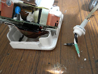
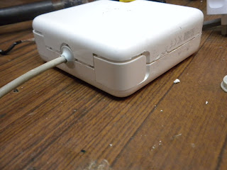
1. Remove the plug from the Magsafe adapter.
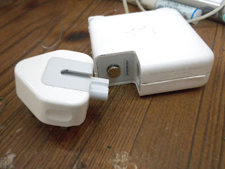 |
| Removing the plug from a Magsafe adapter |
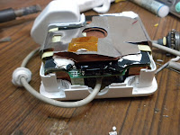
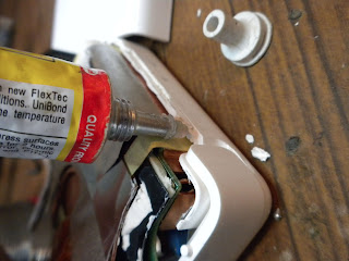
2. Apple have ultrasonically welded the two plastic shells that cover the adapter. They do this by vibrating the two halves against other at such a high rate to melt the plastic at the junction and thus sticking them together. This results in the Magsafe adapter being pretty difficult to open without making some messy cuts in opening it up. So here is a quick tip on opening them up: Flip open the cable tidy arms and insert the pliers into the gap. Then slowly and firmly open the pliers pushing the two parts of the case apart in the process.
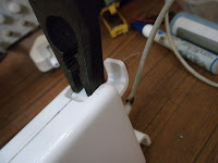 |
| Insert a pliers in the gap for the cable tidy |
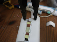 |
| Open the pliers, splitting the case open |
Voila! An opened magsafe adapter with very little tool marking or scratching to the plastic.
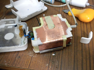 |
| Opened Magsafe adapter |
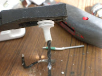
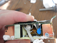
3. Now, bend some of the plastic and copper shielding back around where the cable meets the circuit board to reveal two large solder points. Make a note of where the black cable and the white cable are soldered into the board. To help you, the board should be marked "GND" near the black cable.
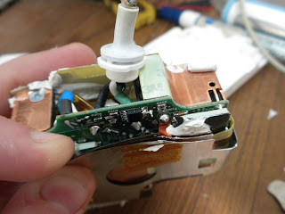 |
| Solder points for Magsafe cable. White is positive, black (GND, cable shield) is negative |
4. Using a high power soldering iron, desolder the two points and gently pull the cable from the board. You may find it easier to solder the points by removing the shielding from the circuit board. I left it on here.
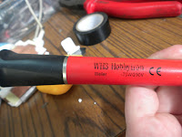 |
| Weller 75w iron |
 |
| Cable successfully desoldered from Magsafe adapter |
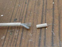
5. Taking the cable, use a sharp knife to make a cut after the break in the cable.
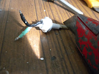 |
| Cutting the good cable from the damaged cable |
 |
| The damaged part ad grommet removed from the cable |
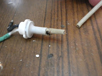
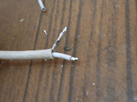
6. Now, using the pliers again, pull the old black wire, and the white wire out of the grommet. You will be left with a hole in the grommet as shown below.
 |
| Removing the wires from the damaged part of the cable |
 |
| The grommet, with the outside insulation of the cable left |
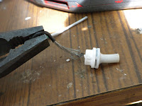
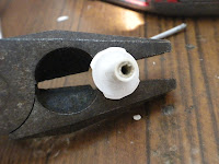
7. Now, drill a hole all the way through the grommet removing the old cable and some of the grommets plastic along the way. You should make the hole large enough to pass the cable through, as shown below.
 |
| Drilling the outside insulation of the damaged cable from the grommet |
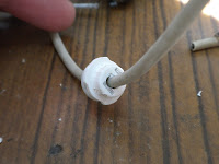 |
| Weaving the good cable through the now cleared hole in the grommet |
8. After you have passed the cable through the grommet, it is time to prepare the cable for soldering back to the board. Using the sharp knife, remove about 20mm of rubber insulation from the cable.
Further remove about 3mm of insulation from the inner white wire. Then tin the ends of both cores using the soldering iron as shown below.
 |
| Removing some outside insulation from the good cable |
 |
"Tinning" i.e. applying solder to the exposed positive and negative cable.
A good tip here is to twist the ends before soldering. |
9. Now, carefully solder both wires back to their respective points on the Magsafe circuit board.
 |
The ends of the cable correctly soldered into place
on the circuit board. |
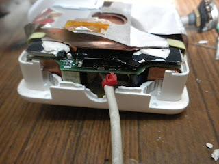
10. Place the circuit board back into one of the plastic shells of the cover. If you have done everything correctly so far, the adapter should be able to charge your laptop as this stage. If you are comfortable testing the adapter while the cover is off, do so now. Or else continue with the guide.
 |
| Placing the circuit board back into one of the covers |
11. Using a small cable tie, wrap it around the cable as tight as you can just inside the plastic cover. This is done so that the cable cannot be accidentally pulled out of the adapter during use.
 |
| Adding a cable tie to the good cable |
12. Run the plastic grommet down the cable back into position in the plastic shell.
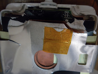 |
| Placing the grommet back into the shell |
13. Using some glue, make a small bead all around the perimeter of the shell. Use the glue sparingly, but cover all the edges where both halves meet.
 |
| Adding glue to the edge of the shell |
14. Press the second half of the plastic shell back onto the Magsafe adapter. Wriggle the two halves to get them into place properly, and then firmly press the two halves back together.
 |
| Squeese the two halves together to make sure that the glue spreads. |
15. Using some large cable ties, wrap them around the Magsafe adapter and tighten them using a pliers. You will need the two halves to be very tight together as the glue dries, or else the two cable tidy arms can fall out.
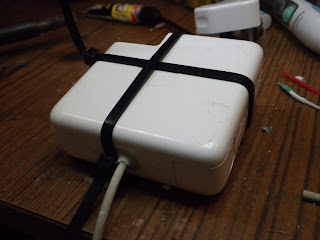 |
| Adding cable ties around the adapter to make sure that they glue together properly. |
16. When the glue has dried, remove the cable ties. You should be left with a working adapter that hardly looks like it was opened at all!
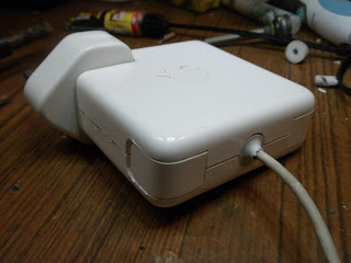 |
| The finished, now working, adapter. |
Unfortunately I accidently ripped some of the rubber off the grommet as I was drilling through it, so go easy on that drilling! I have also repaired a few adapters where the cable has broken and burnt on the connector end. This is a slightly more difficult repair, but I can make a guide if requested.
 I have spoken in a previous blog post about some issues with Apple hardware design here. To briefly recap, it is of my beleif that in general, Apple hardware is very well designed. However, they often overlook functionality in favour of form, sacrificing important aspects such as durability so that "it looks nice". A good example of this is the Magsafe adapter. In a bid to improve aesthetics, Apple shortened the rubber strain-relief grommet that protects the power cable from fraying at the charger end, and the connector end to the laptop. The metal strands inside the cable gradually begin breaking from normal use until eventually, with only a few strands left carrying a large amount of current, the last few strands overheat resulting in a burning smell and the the connection breaking completely. After Apple received many complaints with regard to this problem with the original Magsafe adapter, they extended the length of the rubber on the grommet to improve the durability of the cable. However, in me experience, this wasnt enough: the cable still ends up fraying, and the hardening of the rubber in the grommet over time only aggravates the issue. They also introduces a replacement program, details of which you can find here. However, this does not cover anywhere outside of the United States.


