Monday, April 15, 2019

Cheapest, most ghetto way to Robot Mow your lawn

The task of cutting grass in the summer is an excuse for many to enjoy the outdoors. For me, I would much rather spend my time lying back with a beer on the cut grass. As such, i would get frustrated with the time an effort required to mow our ~600m² with a regular push motor. I looked into purchasing a ride-on mower and then a robot lawnmower. Comparing the two, there are many more advantages to owning a robot mower, to the point where I dont understand why anyone these days would buy a ride-on lawn mower. It is more effort to set up your garden for a robot mower, but are practically maintenance free after than. Ride-ons require the seasonal maintenance that all small petrol engines require such as changing filters, oil, draining fuel, and so on. Robot lawnmowers require no input from yourself while they mow. Although ride-ons are faster to mow that push mowers, they still require your input to control them. The space taken up by a ride-on in a shed is considerable. Lastly, robot lawnmowers cost has fallen to the point where they are cheaper than ride-ons. Due to all these benefits, I looked into getting my garden robot mowed for the smallest cost possible.

I looked to eBay and found a Flymo 1200r mower listed as broken. It was described as failing to power up. I took a gamble and bought it for ~120e with another ~25e for postage through Parcel Motel


It came a week later along with its power supply and base, instructions and nothing else. I was missing the guide/boundary wire and wire clips and connectors, which was what I expected. 


As a first step, I attempted to replicate  the sellers issue. I put the mower on the base station, connected the charger, and powered it up. The display on the mower actually lit up and I could access all the menus after I entered in the sellers PIN number. However, when I took the mower off the base station, the power would die. This suggested that it was a battery issue. 

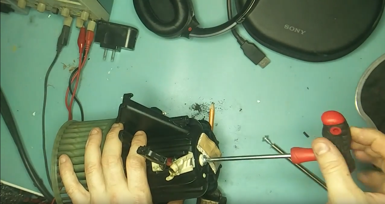
I flipped it over and using a hex screwdriver, I removed the access panel. Beneath it was a USB A connector, possibly for firmware upgrades, and a 5 Cell battery pack. 

Interestingly, the battery was labelled Husqvarna, the parent company of Flymo. A bit of research online suggested that the Flymo 1200r is just a rebadged Husqvarna with more capable firmware. It would be interesting to see if anyone managed to put a 105 firmware on a cheaper Flymo 1200r.
  
Pricing a replacement battery, I gave myself a shock (lol). It would cost me ~65e for a new unbranded one. 
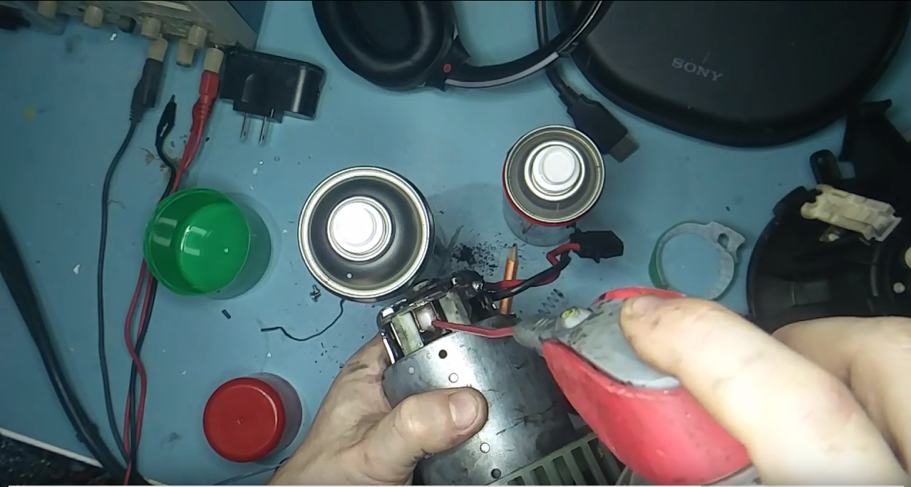
As I was too cheap to pay for this, I began to look into repairing the one I had. I pealed the tape from the battery pack and measured the voltage across each cell. It should be ~3.7v for li-ion. Two of the cells measured ~0v. I figured I would replace all five cells to keep them balanced. I dismantled an old laptop battery and removed its similar "18650" sized cells. I soldered these in place of the faulty ones in the pack and put the pack back into the mower. The originals are the green cells ones below, the red are the laptop replacement ones. The circuit board is the original Battery Management System (BMS) that ensures that each cell charges and discharges at the same rate as each other. 

Unfortunately, the mower would still die when taken off the base station. Dismantling the battery pack again, I discovered that the BMS in the battery pack was not outputting any voltage, even though all the cells were now in working order and sending the pwer to the BMS. This is a safety mechanism of the BMS circuitry. When it detects a faulty cell, like our two found above, it will kill the connection from input and output and call it a day. Some BMS boards allow you to reset them by various methods. Rather than spend the time researching this and perhaps not find a method for my particular board, I bought a similar five cell one off eBay. 

I soldered this in, put the battery pack back together again, and stuck it into the mower. It worked!

Next, the blades needed a service so I removed them with a Philips screwdriver and sharpened them on a water stone used for sharpening chisels and knives. 

After this, I needed a boundary wire to go around the garden. Lets go back to Amazon and see what they have. 

#
Uggh..... 100e for 150m of cable? Yea, no thanks. I went onto eBay and found a fella selling 100m reels of 1.5mm diameter copper cable for 20e. This was for use in wiring in households, but I saw no reason why it would not work as well in the garden. Best of all it was earth cable so it was green to match the grass. I placed an order for 300m worth totalling 60e. When it arrived, I was surprised that two of the reels were blue in colour.


The seller had accidentally mixed up my order and given me two neutral (blue) reels. Right, lets go ahead with this colour anyway- it will keep with the "ghetto" theme. 

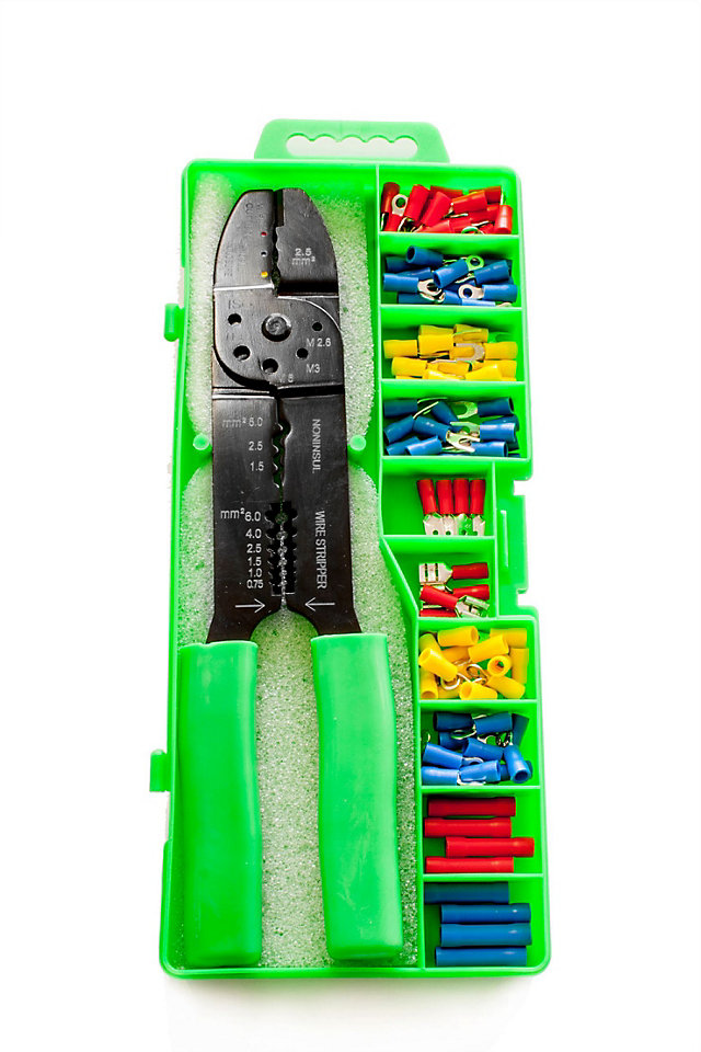
I bought a cheap crimping tool and connectors in Aldi for around 7e. This allowed me to put two connectors on the end of the boundary wire to connect to the base station and another for the guide wire. 

B&Q Crimp tool & connectors, Pack of 101

I still needed to make a few electrical connections to connect the cables together. Flymo sell waterproof connector blocks, similar to below. 


So did we buy these? Of coarse not: too expensive. As I was in Aldi buying their crimping tool, I bought a roll of their "SOS repair tape" for 5e. This is bitumen tape, similar to the "Denso" tape that is used on outdoor electrical connections and indoor plumbing. I use a standard electrical block connector which I then taped tightly with the Aldi tape. 


The "T" connection of the guide wire to the boundary wire was made the same way.  
To peg the wire to the ground, I cut a few 8cm snips of fencing wire, bent them into a long "U" and pinned the cable to the ground with them. This allowed me "fine tune" the position of the wire later on to stop the mower getting stuck in some areas or not cutting others.


Once I was happy with the positioning, I read that the cable should bury itself with grass growth after a few months, but I found that not to be the case in all areas. So I went to the trouble of burying it myself. I used a verge edging tool create a thin channel and then pushed the cable about 20mm under the soil with a small stick.

There was a concrete footpath that I had to cross with the boundary cable and guide wire. I used a junior angle grinder with a diamond disk to cut a channel for the cable and then covered it over again with a small bit of mortar. 


The Flymo 1200r is supposed to max out at 400m² ,but I found that you could set the working time to nearly 24 hours a day if you wanted to use it in a much larger area, like our 600m².

After all that work, the grass is looking great, and the only maintenance that I have to do is to move the mower if I see it stuck the odd time. It is still going strong for over a year. All for around 220e! 

Tuesday, January 29, 2019

Repairing a Shimano Freehub on a Specialized Hardrock Disc 24 speed (2012) bike

The freehub on the back of my Specialized Hardrock Disc 24 speed (2012) bike is on the way out. It grinds when rotated and was full of rusty water when I sprayed it out with the old WD40. I removed it using a spline and a ratchet from the non-drive side of the wheel. 

I re-greased the what I could of the bearings but I reckon its time for a replacement. 


Im pretty sure that these Shimano freehubs are self-contained and have non-replaceable parts. I can just about see the non-drive side bearings on it if I remove the rubber side wall, but there is no obvious way to remove them. I cannot see the drive side bearings at all and again, I can see no obvious way to remove them. Some freehubs have press fitted cartridge ("sealed") bearings, some others have loose bearings. From looking at a photo of a Fast Forward 11 speed hub, https://www.evanscycles.com/fast-for...-body-EV192167, it looks like we can see the red sliver of the side of a bearing cartridge there alright. 

I came across a guide on servicing freehubs on the Park Tool website here: https://www.parktool.com/blog/repair...reehub-service . Comparing their images to the one I have, It looks like I have a Shimano or at least a Shimano type freehub. They said the following about these branded hubs:

"The common Shimano® freehub uses internal loose ball bearing, pawls and springs. Be aware that it is not recommend to completely dismantling the freehub itself. There are no parts available, such as the pawls or springs. The small ball bearings are available as replacement parts. However, if the bearings are worn out and require replacing, it is very likely the entire freehub is needing replacement. The blow-up image seen below is a ball bearing type freehub."


This is a pain, as it looks like I have to replace the whole hub. Id rather a more serviceable hub like the Fast Forward one. So ive narrowed my hub down to a Shimano. To recap, I have a 24 speed bike, or to put it another way, a 8 speed cassette. This website https://bike.bikegremlin.com/1259/bi...compatibility/ and this https://cdn.shopify.com/s/files/1/10...tion_Sheet.pdf appear to state that a 9 speed hub is also compatible with an 8 speed cassette

"9 speed cassette has narrower and more tightly spaced sprockets, so it has the same overall width as an 8 speed cassette"

After a bit more research, I found a freehub on this website that listed it as being compatiable with my Specilized bike. The part details are: 

Specialized S092100009 Joytech 9-Speed 135mm Q/R Sealed Freehub Body

My bike is 8 speed but from what I read earlier in this thread, the 8 or 9 speed freehubs are interchangeable as they are the same width. This is due to a 9 speed chain being thinner. 
I ended up emailing the "regular" bike parts sellers www.wiggle.co.uk and www.chainreactioncycles.com to see if they had it. They all came back to say that they did not have my freehub. So I went with the original website linked above. 

When it arrived, it looked pretty much identical to the original. 


I installed it and unfortunately found that it wouldn't freewheel  The base of it was about .5mm thinner than the the original. This caused it to be mounted too tight against the wheel hub. Luckily, I happened to have a washer from an old table saw that fit. When I sandwiched this between the freehub and the wheel hub and tightened it, it was able to freewheel. 


I put the whole wheel back together and the bike has been running great since. 


Out of interest, I had another go at opening the old Shimano freehub that I removed. I was able to remove the large rubber washer on the drive side exposing a cap that had a key on either side. I was able to unscrew this with a vice and the tool shown below: 


Inside, it was full of rusty water. There were about 20 tiny bearings on each end that looked to be a pain to try and get back together again. The spring on the pawls was rusted and broken. The bearing race channels were pitted. It was unfortunately beyond repair. 

Monday, January 21, 2019

Repairing fuel tank cap on Audi A4 B8

When I had the VCDS USB cable hooked up to the car to diagnose the cabin blower error, I came across a second issue. The VCDS software was reporting that the lock for the fuel cap was acting up. A print out of the error was as follows:

Address 46: Central Conv. (J393)       Labels: 8K0-907-064-46.clb
   Part No SW: 8K0 907 064 A    HW: 8K0 907 064 A
   Component: BCM2 1.1      H70 0134  
   Revision: 00002001    Serial number: 010967865308    
   Coding: 0100062000390040012001
   Shop #: WSC 06325 000 00000
   VCID: 2E4A198B2017BC72BDAC28D-807B

3 Faults Found:
02615 - Fuel Tank Cap; Lock 
            009 - Open or Short to Ground
             Freeze Frame:
                    Fault Status: 01101001
                    Fault Priority: 2
                    Fault Frequency: 1
                    Reset counter: 128
                    Mileage: 264877 km
                    Time Indication: 0
                    Date: 2018.12.28
                    Time: 22:48:18

02616 - Fuel Tank Cap; Unlock 
            009 - Open or Short to Ground
             Freeze Frame:
                    Fault Status: 01101001
                    Fault Priority: 2
                    Fault Frequency: 1
                    Reset counter: 128
                    Mileage: 264877 km
                    Time Indication: 0
                    Date: 2018.12.28
                    Time: 22:51:58

It appears thtat the fuel cap was not locking itself. Not really a problem, I mean, who siphons fuel to steal it these days. But it would be good to repair it nonetheless. I needed to have a look at the fuel cap lock to see what was wrong. If you open the cap, you will see a single screw that you can remove on the plastic panel.

Once this is done, using a spudger or blunt knife, remove the plastic panel. You will see the lock module on the left (model 8K0 862153 F). Slide this to the right and lift it out. It will be connected by a red plastic cable. Unclip this on the module side. Now you can remove it from the car.


If you are replacing the module, you can just follow the instructions in reverse to put it back in. I opened by module to see what the issue was. There are clips around the perimeter of the module.

Unclip these and remove the cover. Inside is a motor and lock mechanism.

To remove the motor, pull out the two pins in the plug (like above, with a needle nosed pliers) . Then you can wiggle the motor out of the module housing. I removed the motor and attempted to spin it with a 12 v power supply. I would spin, but only after a push. Monitoring the power supply, I notices that it current limiting was it was pulling more than 2 amps at certain angles of the armature. This is a sign that the coil was shorted or burnt out.

I doubt that I would be able to get a similiar motor, and it would be a pain to remove the gear and put it onto a new one, so I just bought a replacement module for about 30e.


Repairing a faulty cabin blower in an Audi A4 B8

While driving I noticed that the fan in the cabin of the Audi A4 was becomming tempermental. 50% of the time when I would press on the button to demist the front windshield it would fail to start up. I hate having to wipe the glass as it leaves streaks, so I was forced to drive with the windows wound down to get enough air through the cabin to clear the glass. Not the safest of options.

I got the laptop out, connected the VCDS cable and ran the software. I got the following error related to the Heating, ventilation, and air conditioning (HVAC) module in the car.

Address 08: Auto HVAC (J255)       Labels: None
   Part No SW: 8T2 820 043 K    HW: 8T2 820 043 K
   Component: KLIMA 1 ZONE  H05 0120  
   Revision: B0000000    Serial number: 0126.02.080837
   Coding: 34040000
   Shop #: WSC 06325 000 00000
   VCID: 3A6225DBEC5F60D2112454D-806F

2 Faults Found:
01273 - Fresh Air Blower (V2) 
            003 - Mechanical Failure - Intermittent
             Freeze Frame:
                    Fault Status: 00100011
                    Fault Priority: 3
                    Fault Frequency: 55
                    Reset counter: 179
                    Mileage: 264877 km
                    Time Indication: 0
                    Date: 2018.12.29
                    Time: 16:27:51

             Freeze Frame:
                    Temperature: 11.0°C
                    Speed: 0.0 km/h
                    Load: 0.0 %
                    Load: 8.5 %

01273 - Fresh Air Blower (V2) 
            006 - Short to Plus - Intermittent
             Freeze Frame:
                    Fault Status: 00100110
                    Fault Priority: 3
                    Fault Frequency: 14
                    Reset counter: 179
                    Mileage: 264877 km
                    Time Indication: 0
                    Date: 2018.12.29
                    Time: 16:27:53

             Freeze Frame:
                    Temperature: 11.0°C
                    Speed: 0.0 km/h
                    Load: 0.0 %
                    Load: 32.5 %
                    Voltage: 11.60 V

Googling keywords from the issue informed me that the fan/blower motor had to be replaced. New, this part is about 120e off ebay. To do this, I would need the part number to look for. So I would have to take it out to have a look at it.
I roughly followed this guide here to remove the glove compartment. https://www.youtube.com/watch?v=9d3zL-7kJBQ Note, some guides will advise you to remove the Radio to get at some bolts. I did this, but found that there were no bolts that needed removing. So dont do that.
there are about 5 screws to remove from the glove compartment. Two on top, about two on bottom, and one under the panel to the left of the compartment inside the door. Once removed, you will need to disconnect a cable going from the car to the airbag enable/disable switch in the glove compartment. Once this is removed, put the glove compartment aside. You will see the power resistor for the fan and the fan itself. One screw holds the fan. Remove this, and then with two hands, firmly twist the fan housing to remove the whole fan. The blower/fan will look like the following:

I cleaned out the cage for any debris. I spun the fan by hand and found that it was very stiff, only spinning for less than one second before stopping again.


I hooked it up to a 12v power supply limited at 2 amps and found that it turned slowly.


Looking at the part number, it is 8k2 820 021. This is not meant to be a user serviceable part, but as I had nothing to loose, I decided to open it.
I removed the back cover, it is held in place by two screws


I bent back the two copper gates holding spring for the carbon brushes in place. This allowed me to remove the spring and spray some WD40 into them to make sure that they came in and out freely. The brushes had about half their life left. Leave the springs out along with the brushes pulled out.
I then sprayed the bushing closest to the cage too
Next, I decided to have a look at the rear bearing and the commutator. To do this, we have to remove the back piece of metal covering the rear bearing. This is held in place against the main housing by a few crimps in the metal. These can be teased up by a flat screwdriver. Unfortunately, I do not have any photos or video of this.
You will now be able to see the commutator. You can see that there is alot of carbon buildup on the copper, along with wear patterns from the brushes.

This can be cleaned with a bit of sandpaper. I put the cage end into the chuck of an electric drill, held the sandpaper against the commutator, and spun it to smooth and clean it.

Then I used a dental pick to clean between the copper contacts on the commutator for any bits of copper or carbon that might short it.

The rear bushing got spray of wd40 too. I pressed the rear metal housing back into place again. This will require a few goes and some patience. A few taps of a small hammer bent the crimps back into place.

Screw the rear black plastic housing back into place again. I tested it with the power supply again and it appeared to spin with more speed. Manually spinning the cage resulted in it continuing to spin for 2-3 seconds before coming to a stop. Not great, but definitely better than before.

I installed it back into the car. VCDS along with the cable was used to reset the all errors on the car. After a month of use, the fan works now as expected, and there are no errors showing up on VCDS. Success! 

Friday, November 25, 2016

Repairing Audi A4 B8 8K door not unlocking with remote fob

When you buy a pretty premium saloon, you would expect reliability. However, I have found that the german engineering of the Audi a bit underwhelming in terms of both reliability and ease of repair. Too often, small little niggley things have given up the ghost on the A4. The latest to go was locking mechanism on the drivers side door. When I tried to unlock the door with the remote key fob, the door made made a grumble but failed to unlock. It would require a second press of the fob to unlock the door, or else it wouldnt open at all. Instead, I would have to roll down the windows with the fob and open the door by reaching in and opening it from the inside.
I also noticed that the automatic locking of the door when the vehicle went over 30kph was making a strange noise on the drivers side.

I tried a few different solutions outlined on the various forums:

  • Pull the outside and inside handle at the same time until you feel it click: This appeared to work for a while, but failed again. 
  • Spray WD40 over all the moving parts including lock tumbler and handle cable: No effect
  • Dismantle door lock module and grease all parts: no effect
Using the VAG-COM VCDS diagnosis software and cable, I found a that the door lock module was throwing a "outside limit" error. Worse again, after a while, the issue appeared in the passengers side door too. Due to the noise that the locking mechanism made, I suspected the door motor. As such, I removed the trim and then the paneling of the door. There are about 6 torx screws that you have to remove to unfasten the paneling. Then you have to start pulling out the panel from the bottom. once you get the top, you can lift it upwards to remove it. Next, you can remove the blue internal door handle cable by unhooking it from the door handle side. Once that is done, you have to remove the outside door handle cable from the lock module. Reach into the door frame and twist the yellow catch on the end of the cable going into the door lock module. Next, remove a rubber gromit on the edge of the door frame to expose a grub screw securing the lock tumbler. Loosen this, and pull out the lock tumbler from the outside. Then to remove the door lock module, you will have to remove two large bolts from the outside edge of the door frame. Then you can reach in and remove the loosened door lock module.

Take the module to your work bench and remove all the screws on the outside. Open up the small gray hatch window. You will see two axels coming out from the main housing into the locking mechanism. Insert a flat screwdriver and prise the axels from the lock mechanism. You will be left with just the main housing. Using a spludger tool, prise the two half of the housing apart. Inspect the two halves when apart- if the water proof gromit has come loose, press it back into place.

Inside, you will see the two motors of the module. Remove the largest. Clean the two contact that insert into the motor. I used some fine (2000 grit) sandpaper. At this stage, I tested the motor using a 12v supply and found that it struggled to turn without help. There was obviously something wrong with it. Using a small screwdriver, lift the two tabs on the end of the motor. You can then prise the end off the motor. There was much carbon dust in the motor from the brushes. As such, I tapped the motor on the desk to knock it out. The commutator on the motor was blackened from the brushes. Again, with the fine grit sandpaper, this was quickly cleaned up. You can remove the brushes with a sim card removal tool. I cleaned these up with a small rag. I put the motor back together and tested it with a 12v supply. It ran perfectly.

Finally, you can put everything back again. Using the VAG-COM VCDS diagnosis software and cable, I reset the error codes. I tested the door, and it worked perfectly!. A month later and it still hasnt given any problems or caused errors in VCDS.

Note: I had a second door stop unlocking that the guide above did not repair. Instead, I had to replace the "bowden cable" to fix this. You can see it in the photos below with the sky blue rubber around it. It appears That these do not move smoothly enough after a few years to allow the lock to reset back to its previous position.